Background/Motivation
When I discovered the CyberBrick™ toy ecosystem, I was so fascinated by it, mainly because I have kids and the keyword toys. With a 3D printer, I can now make some little toys from time to time to keep my kids entertained. Of course, I love making things, so it’s not entirely for my kids—it’s an excuse to justify this newly found hobby.
Anyway, to get started as a developer under the CyberBrick™ ecosystem, you need a basic working system to play around with.
Of course, you can check the official CyberBrick Wiki here, however, the information is rather scattered and it lacks a clear picture about how to get started as a developer.
Therefore, this is the motivation for this quickstart guide (Basically, this is just a record of how I got started).
Big Picture
What is CyberBrick™? CyberBrick is a modular smart toy ecosystem that combines programmable hardware, 3D printable structures, and dual-level coding environments. It is where 3D printing collides with electronics and coding through LEGO-like simplicity. CyberBrick empowers anyone to build and enjoy a wide range of 3D-printed projects, from R/C toys to productivity tools.
The way I understand the CyberBrick toy ecosystem is that there are three aspects to it:
- Electronics Hardware: i.e., the official component list that allows you to do a variety of things. But in simple terms, it’s just an input→process→output kind of system.
- Programming Software: Programming how the components interact with each other by using CyberBrick Desktop Software. The desktop version is used because only the desktop version can
Create New Project. - 3D Printable Structure: Basically, it should be the appearance of your idea/design. Of course, there could be a mechanical part that is 3D printed.
Getting Started
I’ll focus on aspects 1 and 2 from the above big picture. That is, just build a very simple input → process → output system out of the official component list and use CyberBrick Desktop Software for the process part.
Simple Test System
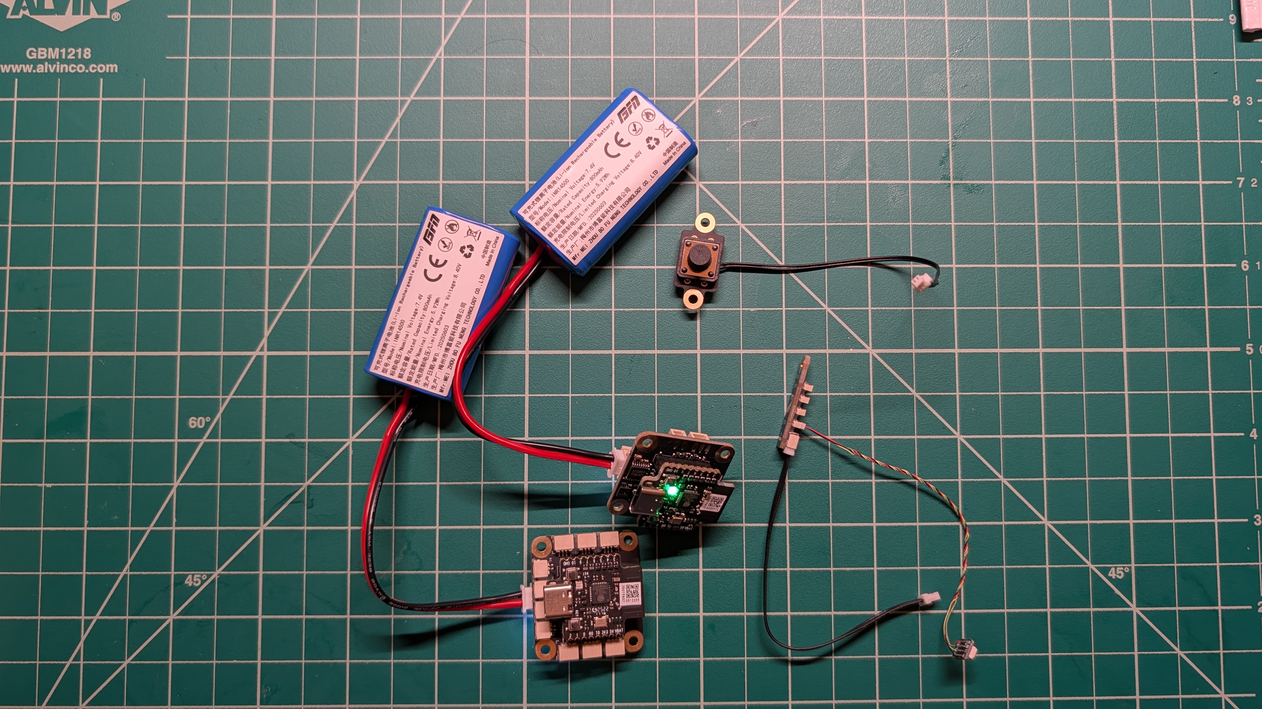
Okay, let’s design a bare-bones system with input as a button and output as an LED.
The process part is just “if a button is pressed, an LED lights up”. Basically, a button at the transmitter (TX) side is pressed, then an LED at the receiver (RX) side will light up.
Now, someone may ask: Do we really need an RX/TX system to implement the above simple system? The answer is absolutely no—you can of course do it with just one Multi-Function Core Board - XA003 with both button and LED connected to the same board. But this requires “custom” changes to the official component list. The idea here is to just really use whatever the “bricks” we have and implement a system.
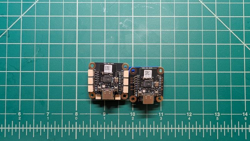
Hardware List
Please note that the Remote Control Transmitter Shield - XA003 XA005 and Remote Control Receiver Shield - XA003 XA004 are already mounted on individual Multi-Function Core Board - XA003.
Software Setup
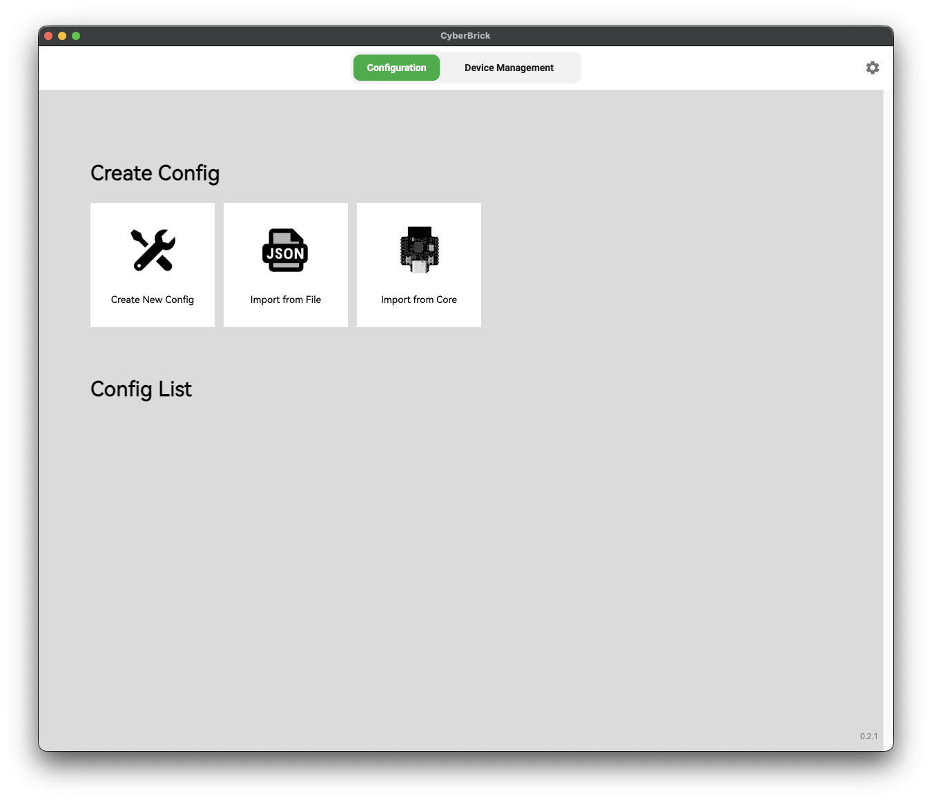
Download and install the CyberBrick desktop app and open the app.
Now, what we need to do is add the TX and RX devices to the Device Management as shown below.
Then Create New Config → Start from empty.
Then in the Channel Config tab, + Add Receiver.
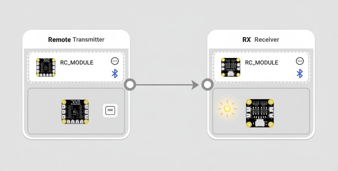
In the Controller Connection tab, you can now drag and drop the TX/RX to the corresponding boxes.
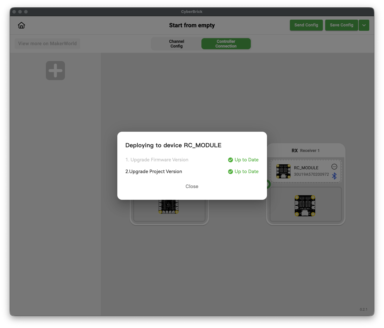
You may need to upgrade the firmware when adding the devices.
Finally, just check Pair device.
Programming
Now, the last part, which I also think is not clear in the official wiki, is how to program the TX/RX to behave as we want, i.e., “if a button is pressed, an LED lights up”.
First, add a button to the TX, then add an LED to the RX.
After you add an LED to RX, you can define how the LED behaves, or it’s called Effect in the software. Pick a name for this effect—in my case, I use Blink_Red.
Now, back to the TX, you can finally program “if a button is pressed, an LED lights up”. In the software, it’s called an Event. For a button, you can select certain types of “button events” from the dropdown list.
Now, simply select Press as the Event, LED1 as the Module (you can think of which module will respond to the Event).
Finally, the Value is just the behavior of the LED1 that we defined before, which is Blink_Red.
Finally, just Save Config and Send Config to both TX/RX. Then you are done.